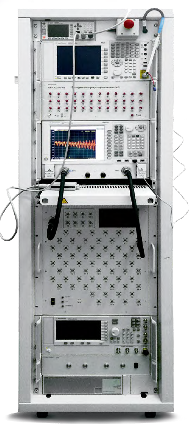
◄ Fully automated system for testing RF parameters of transmit/receive modules and transponders.
◄ More than 10 measurement types, more than 30 measured parameters.
◄ Unique methods of path calibration and correction.
◄ Automated recorrection for calibration plane displacement and distortion elimination inside the track.
◄ The highest testing velocity in the market
Description
PTS series payload and PCB testing system offers the highest quality and velocity in RF parameters testing of transponders in frequency range up to 40 GHz with automated path recorrection and in frequency range up to 50 GHz with traditional path calibration.
PTS series payload and PCB testing system provides the following parameter measurements:
◄ Input/output saturation level – measurement inaccuracy 0.2 dB
◄ Input/output compression point level – measurement inaccuracy 0.2 dB
◄ Gain ratio – measurement inaccuracy 0.2 dB
◄ Noise ratio – measurement inaccuracy 0.2 dB
◄ Amplitude frequency characteristic in linear gain mode – measurement inaccuracy 0.2 dB
◄ Amplitude frequency characteristic in gain saturation mode – measurement inaccuracy 0.2 dB
◄ Amplitude frequency characteristic compression point – measurement inaccuracy 0.2 dB
◄ Phase noise – measurement inaccuracy 0.3 dB
◄ Group delay/Group delay ripple – measurement inaccuracy of less than 0,5 ns
◄ Signal to noise ratio – measurement inaccuracy 0.4 dB
◄ Beacon frequency and power measurement
◄ Tertiary and quintic ntermodulation distortion – measurement inaccuracy 0,2 dB
◄ Out-of-band radiation
◄ Input/output reverse losses
◄ Digital frequency modulation error vector (vector generator added to the system)
Advantages
At transponder parameters measurement choice of the measurement system is defined by its accuracy and operation speed.
One of the key points in transponder measurement is large dimensions of the device under test as well as necessity to perform tests inside a climatic chamber, which makes using long RF cables with high losses and a range of connection adapters a must. Under such conditions the factor of systematic calibration error of the system grows due to inaccuracies in connector plugging and track characteristics distortion. PTS series payload and PCB testing system employs unique patented methods of calibration and track distortion elimination, which allows to get the lowest inaccuracy values in the industry.
Another critical factor is measurement speed and logging of results. PTS series payload and PCB testing system offers cutting-edge software adapted to Russian language RL-NAS version 2.0, it creates measurement status files that contain calibration data, devices settings parameters etc., which allows to minimize system set-up time. RL-NAS software automates measurement process using custom settings of the measurement cycle order; client/server computing allows to log results with a display of transponder parameters configuration.
System configuration flexibility provides for testing of transponders with various channel numbers from 1 to 70 on the input and from 1 to 70 on the output.
Characteristics
| Model | PTS-130 | PTS-260 | PSN-400 | PSN-500 |
| Frequency range | 10 MHz – 13 GHz | 10 MHz – 26 GHz | 10 MHz – 40 GHz | 10 MHz – 50 GHz |
| Stimulus signal maximum level | +13 dBm | +13 dBm | +12 dBm | +10 dBm |
| Dynamic range at transmit parameters measurement | 130 dB | 130 dB | 125 dB | 120 dB |
| Inaccuracy at transmit parameters measurement | 0.2 dB | 0.5 dB | ||
System configuration
Basic configuration of the system allows testing the following parameters:
◄ Input/output saturation level
◄ Input/output compression point level
◄ Gain ratio
◄ Amplitude frequency characteristic in linear gain mode
◄ Amplitude frequency and phase frequency characteristics in gain saturation mode
◄ Amplitude frequency and phase frequency characteristics in compression point
◄ Input/output reverse losses
Measuring options
Option PTS-NF adds noise ratio measurement function
Option PTS-PN adds measurement of off-band radiation phase noise function
Option PTS-MY adds beacon parameters measurement function
Option PTS-GVZ adds group delay measurement function
Option PTS-SNR adds measurement of off-band radiation signal to noise ratio function
Option PTS-IMD adds measurement of intermodulation distortion function
Option PTS-VSG adds measurement of digital modulation error vector function
Hardware options
Option PTS-MatrixIN adds switch matrix for input signal routing (number of channels is decided by the customer)
Option PTS-MatrixOUT adds switch matrix for output signal routing (number of channels is decided by the customer)
Option PTS-AutoCAL – adds automated calibration and recorrection of RF track parameters (number of calibrated channels is decided by the customer)